SSL certificate ACTIVE  

Below are a range of Peco point motors which consists of a metal bar passing through two coils. When a 16 volts AC supply is connected to one of the coils the metal bar slides to one side. When the same 16 volts AC is to the other coil the metal bar moves in the opposite direction.
Other makes are available but they all carry out the sae function switching point blades.
The sliding bar is connected to the point by the vertical thin pin passing through the hole in the moving tie bar of the point and the feet of the motor fit into the slits in the frame of the point.
When fitting a Peco PL10 point motor to a Peco ’00’ gauge point fold over or cut off the centre pair of tags and only use the four outer tags. When fitting a Peco PL10 to a Peco ‘N’ gauge point use the centre pair of tags and a pair at one end. The pair at the other end are not used and can be cut off or bent over.
This point motor can be mounted directly under the point or sandwiched between base board and point. 
If the point motor is mounted directly under the point a ‘cutout’ must be made in the baseboard big enough to allow the point motor to fit through. The unit can be fitted to the point and tested before the point is installed on the baseboard. Although the best it is not always possible because of timber supports directly below the point position.
The image on left shows the Peco PL10 point motor attacked directly to the bottom of the streamline point.
A switch (see lower left) if required can be fitted to the bottom of point motor
The switch can be used to feed supply to the frog when using ‘live’ frog points.
It could be used to switch colour light signals or an indicator lamp on a control panel indicating which way the points are set
An alternative to the above is when the point motor is mounted on an plate which is screwed directly on to the underside of the baseboard and positioned so the pin on the point motor passes throught a small hole around 6mm and into  the hole in the point tie bar.
As this requires a point motor with a longer pin  you will need a PL10E. Your dealer will know what you mean; just say you are mounting it under the  baseboard. 
When space under the base board is restricted you can mount the Peco point motor PL10 on a mounting plate fixed to the side of point.  This could make wiring easy with solded joints at eye level.
Also a Peco switch could be mounted on top of point motor which could be used to switch feed to the frog on ‘electofrog points.
The assembly could be housed under a line side building.
There also a point motor available from Gaugemaster which is designed for underboard mounting and has a built in switch and only requires a small hole through the base board to allow movement of the point tie bar.
It is known as a Seep point motor.
The two point motors fitted to points above are side mounting for use when space underneath the base board is limited.
The one on the right is the standard PL10 mounted on a base plate and hooks onto the end of the point tie bar and because it is a PL10 it has a stronger pull/push than the other one.
The point motor on the left is a PL11 which is designed to fit on the side of Peco points.
When a point motor is switch by push button or 2P2W centre off biased switch they require a good supply as they demand a high current capacity to operate correctly.  To ensure this happens two things are important
  1. Thick cables linking the supply (or CDU if fitted) via a switch to the point motor to ensure there is very little volts drop.
  2. A ‘CDU’ (capacity discharge unit) shown on the right is highly recommended wired between the 16VAC supply to the push button/switch and from switch to point motor so when the point is switched there will be plenty of voltage/current available. (see image on right)
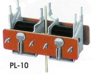
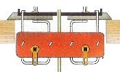
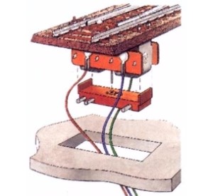
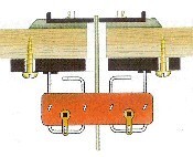
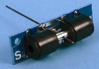
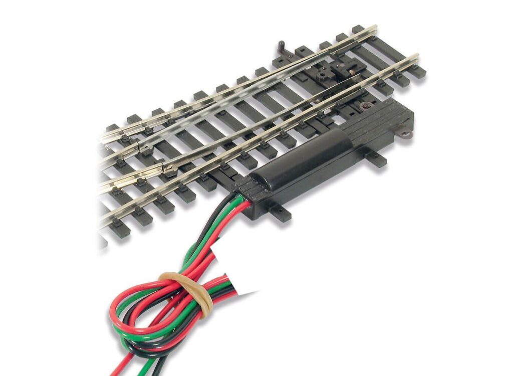
The ways of switching the points is a sort of switch that will send 16 VAC to either one side or the other side of the point motor. (see on left)
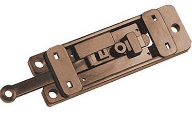
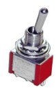
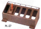
This can be in the form of (A) a 2P2W centre bias switch (B) two push buttons (one for each way) on a control panel , or (C) a ‘passing contact’ switch
See ‘Controls and wiring’ section on how to connect above components to controls.  Press quick link on right to go directly there.